An example is provided below to illustrate how critical the patent drafter’s skills are. The example is not meant to be a comprehensive illustration of all aspects of the matters discussed in this article. Doing so might require a book or an entire course. Instead, the example is used to highlight a single point regarding the scope of a patent claim using an artificially simple context.
The reason why I call the example artificially simple is that the technology involved is made very simple for the purpose of illustration. Most inventions today involve much more complicated technologies, only making the point illustrated here much more acute in reality.
In addition, writing broad claims is only a part of a patent attorney’s job. This particular point is selected for illustration in the following example only because the point is relatively easy to illustrate. In reality, preparing a strong patent is much more than writing broad claims.
Now the story:
Once upon a time, an inventor decided that the conventional air duct of a laundry dryer should be improved.
As we know, a laundry dryer exchanges air with the outside environment. It takes in regular air and releases hot air. A laundry dryer is typically used inside of a room. Because the hot air released by a laundry dryer is generally unclean and unsuitable to be released inside the room, it is usually released through a long air duct passing through a wall to the outside. For this to happen, the air duct necessarily has an opening that is exposed to the outside.
This causes a problem during the cold winter. While the opening of the air duct releases hot air to the outside when the dryer is in operation, it also allows the cold air from the outside to enter into the room when the dryer is not in operation. This undesirably lowers the temperature in the room, or increases the amount of energy required for heating the room.
A natural solution to this problem would be having a valve on the opening of the air duct such that the valve normally keeps the opening closed but opens up only when the dryer is in operation. But the problem with the solution is that such a valve might require someone to go outside of the room to open or shot the valve every time when needed. Most people would probably rather live with a slightly higher heating bill than going outside during a cold wintertime to perform such operations.
Our inventor had a great idea to solve this problem. His idea is illustrated in the following figure:
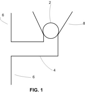 As shown in FIG. 1, our inventor introduces a floating ball valve (2) to the air duct (4) that is connected to a wall (6). The floating ball is made of a light material. When the dryer is not in operation, there is no hot air flowing through the air duct, so the floating ball sits over an opening of the air duct and closes it to prevent the outside air from entering the air duct.
When the dryer is in operation, hot air blows through the air duct as indicated by the arrows in FIG. 2. Because the floating ball is relatively light, it is lifted up by the hot air flow as shown in FIG. 2.
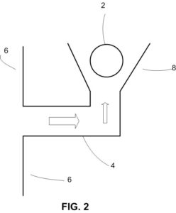
The lifted floating ball enters into a tapered section (8) of the air duct and remains suspended as long as there is an upward hot air flow blowing against its bottom. This leaves the air duct open so that the hot air can pass through the air duct into the outside. When the dryer stops its operation, the hot air stops to flow and the floating ball falls back to its sitting position as shown in FIG. 1 to close the opening again.
Voilà, an automatic hot air valve! The inventor describes his invention to his patent attorney, who then writes a patent application that claims the following:
An air duct valve for a dryer, comprising:
a horizontal air duct section connecting to the dryer through a wall;
a tapered vertical air duct section connecting to the horizontal air duct section, the vertical air duct section having a smaller opening connecting to the horizontal air duct section and a larger opening communicating to an outside environment; and
a ball of a light material placed within the tapered vertical air duct section, the ball having a diameter greater than the smaller opening but less than the larger opening, wherein when there is no hot air flowing from the horizontal air duct section, the ball sits over and closes the smaller opening, and when there is hot air flow from the horizontal air duct, the ball is moved away from the smaller opening and floatingly suspended in the tapered air duct section such that the hot air can pass through the tapered air duct section to enter the outside environment.
Sounds like the claim captures exactly what has been invented.
Sometime later, to the shock of our inventor, a company starts to make and sell an air duct system as shown in FIG. 3:
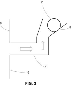
Instead of using a floating ball, the company uses a rolling ball that rolls up and down on a sloped surface depending on the hot air flow.
The inventor knew the company stole his idea. So he sues the company for infringement.
There is no infringement. To infringe the claim, the alleged infringing product must have each and every element that is recited in the claim. The company’s product does not have a tapered vertical air duct section. It has a tapered section, but that section is not vertical. More significantly, the company’s product does not have a floating ball as claimed. When there is hot air flowing from the horizontal air duct, the company’s ball is moved away from the smaller opening, but it is not floatingly suspended in the tapered air duct section, rather it is rolled up against a slope surface.
The end of the story: the company made lots of money selling an improved dryer air duct system, secretly thanking the information made public by the patent issued in the inventor’s name. The inventor lost market to the company, in addition to suffering losses in legal fees.
The company is clever. But the patent attorney is at fault. He failed to grasp the fundamental concept of the invention, which is the inventive utilization of gravity in this case, rather than a particular shape of the air duct, or of the ball for that matter. Had the patent attorney understood this basic aspect of the invention, he might have written a claim like below:
An air duct comprising:
a tube including a neck having an open diameter communicating to an outside environment; and
a movable valve placed within the tube, the movable valve having a gravitational tendency to sit over the neck to block the open diameter, and capable of being moved away from the neck by an air flow toward the outside environment to allow the air flow pass through the open diameter.
The above claim captures the essence and the spirit of the invention and is now definitely infringed by the competitor’s product. There is no way anyone can steal the basic concept of the invention without infringing the above “lean and mean” claim. The claim is “airtight,” so to speak.
The above example is probably overly simple. In most other inventions, capturing the essence of the invention may not be as simple as seeing gravity in the mist of some structures and shapes as in the above example. But the example illustrates an important point why a good patent attorney makes a difference.